TEST SYSTEMS

Test systems engineered around your mission.

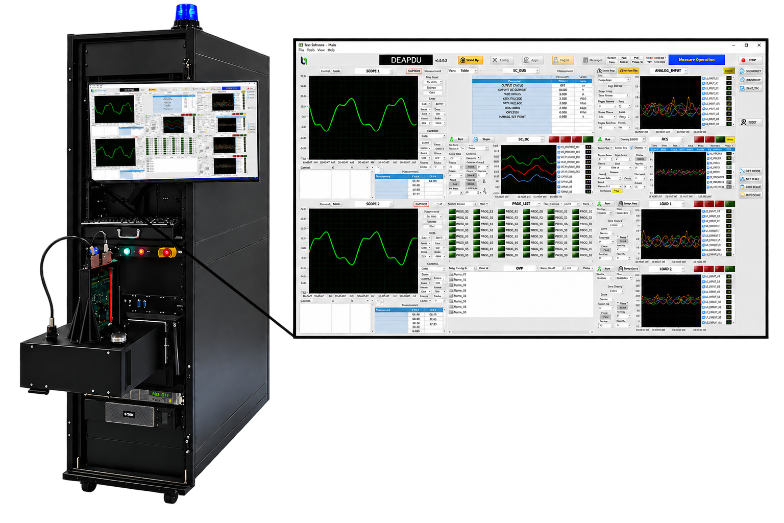
B&A Engineering designs and integrates complete test systems for aerospace and space hardware testing — built around B&A-developed products, extended with mission-specific custom hardware, and completed with carefully selected COTS equipment.

TEST SYSTEMS

The right test system platform for the test.

Configure the system around size, mobility, instrumentation and interface requirements.

01 / STANDARD SINGLE RACK

Standard Single Rack

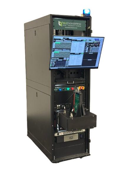
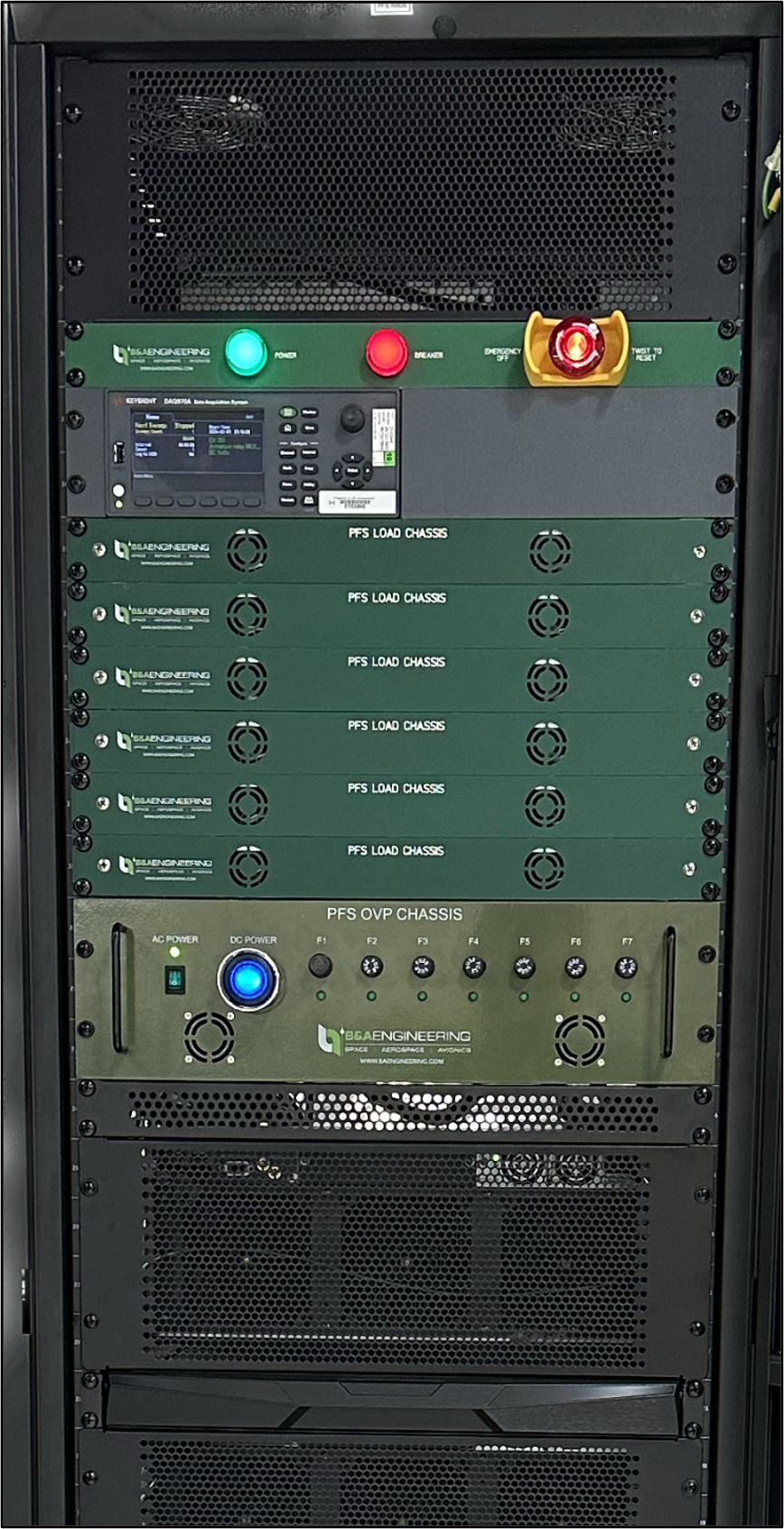
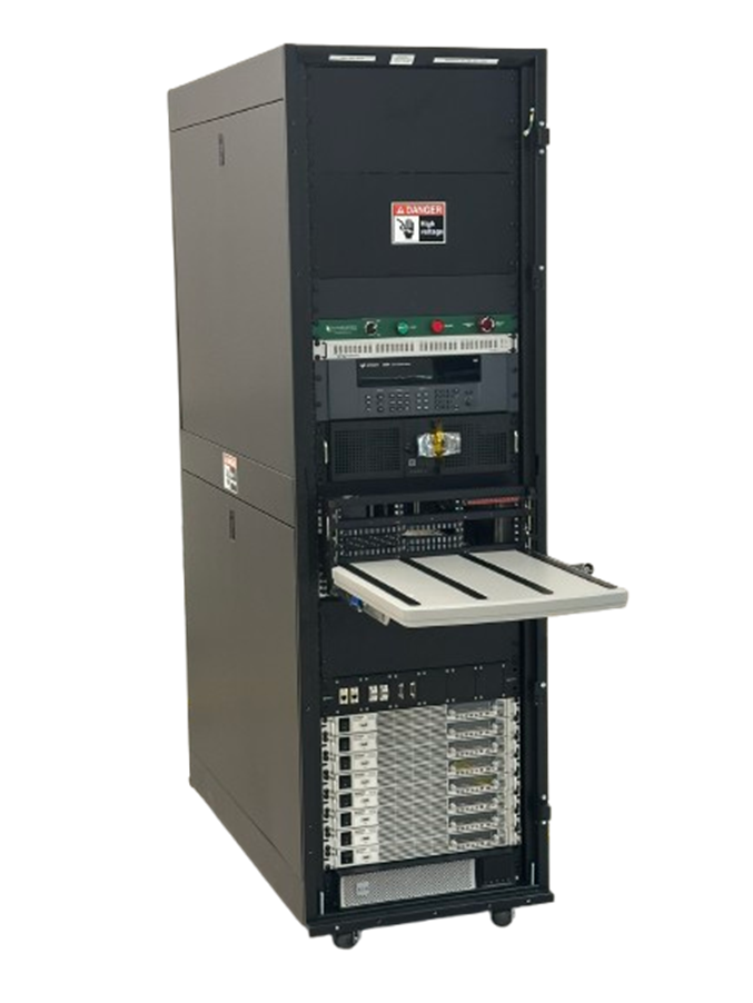
Standard 19-inch rackmount test system with up to 42U of equipment space for integrated test configurations.

02 / MINI RACK

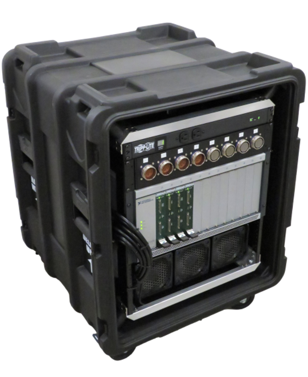
Mini Rack

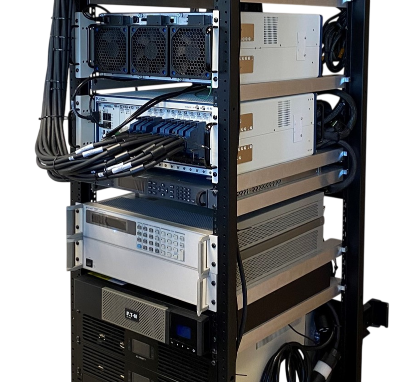
Compact portable rack-based test system with integrated power, interfaces and instrumentation.

03 / MULTI-RACK

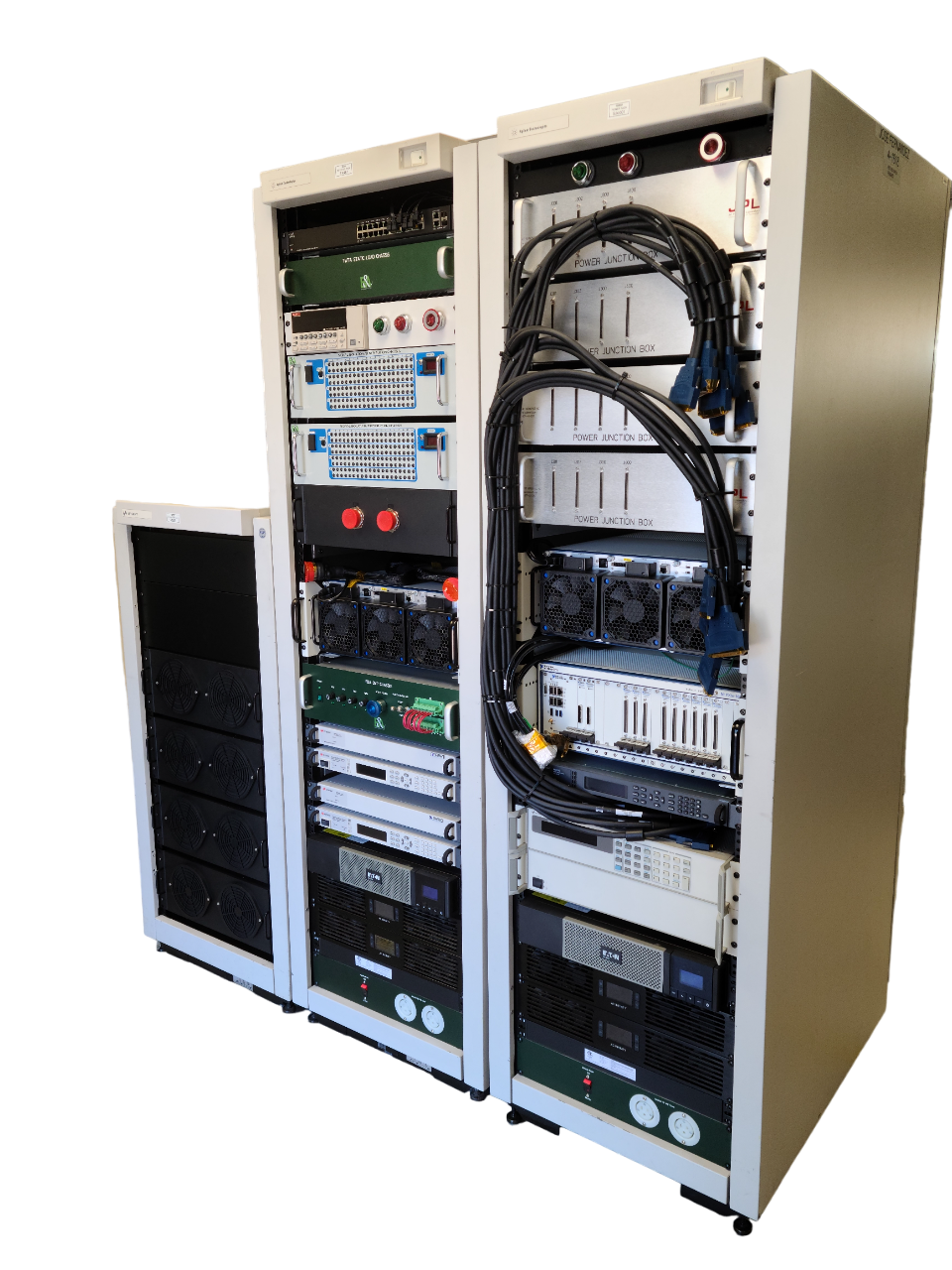
Multi-Rack Systems

Integrated test system distributed across multiple racks for larger test systems requiring additional equipment, interfaces, power distribution and instrumentation.

04 / BENCHTOP

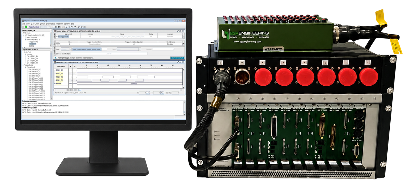
Benchtop Test System

Compact benchtop test system platform for development, troubleshooting, interface testing, and smaller test configurations without requiring a full rack system.

INTERFACE TO DUT

Flexible interfaces between the test system and DUT.

B&A supports two interface architectures depending on test-system reuse, DUT configuration, cable complexity, and program requirements.

01 / VPC RECEIVER + ITA

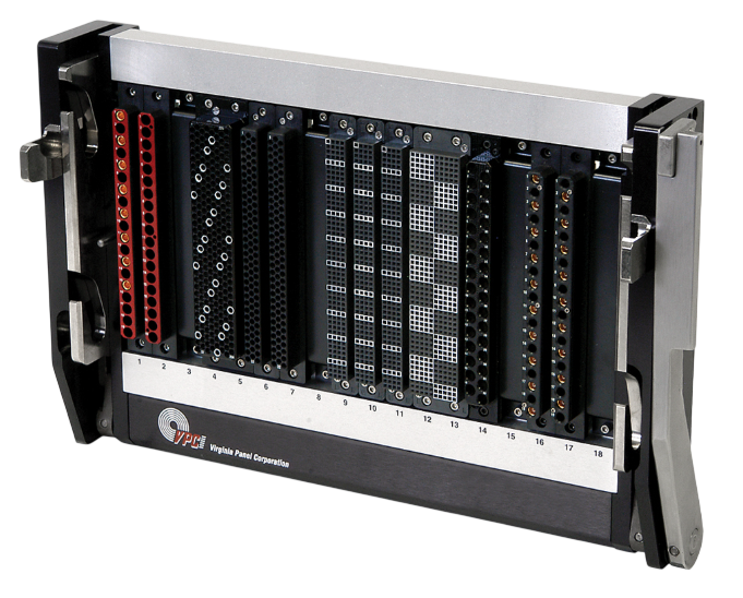
Interchangeable Test Adapter

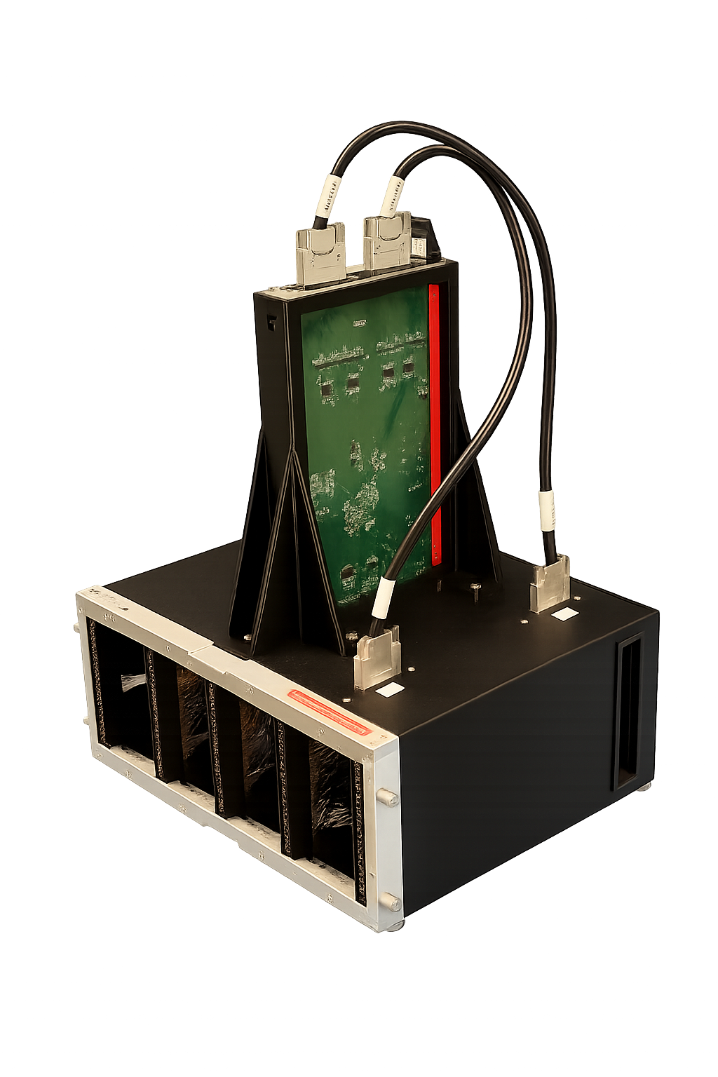
Virginia Panel Corporation (VPC) receiver and ITA architecture provides an industry-proven modular interface between the test system and DUT. The ITA frame is mounted to the test system rack, as shown above, and accepts interchangeable DUT-specific ITA boxes. A DUT — for example, an electronic board — can be designed to mount directly to its dedicated ITA box. Changing the ITA box allows the same test system rack and interface frame to support multiple DUT configurations.

TEST SYSTEMITA FRAMEDUT-SPECIFIC ITA BOXDUT / BOARD
02 / B&A INTERFACE CHASSIS

B&A Interface Chassis

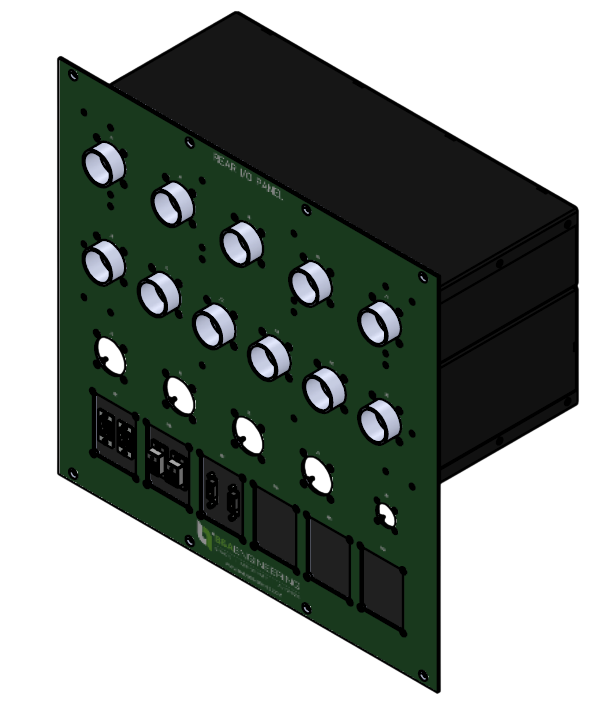
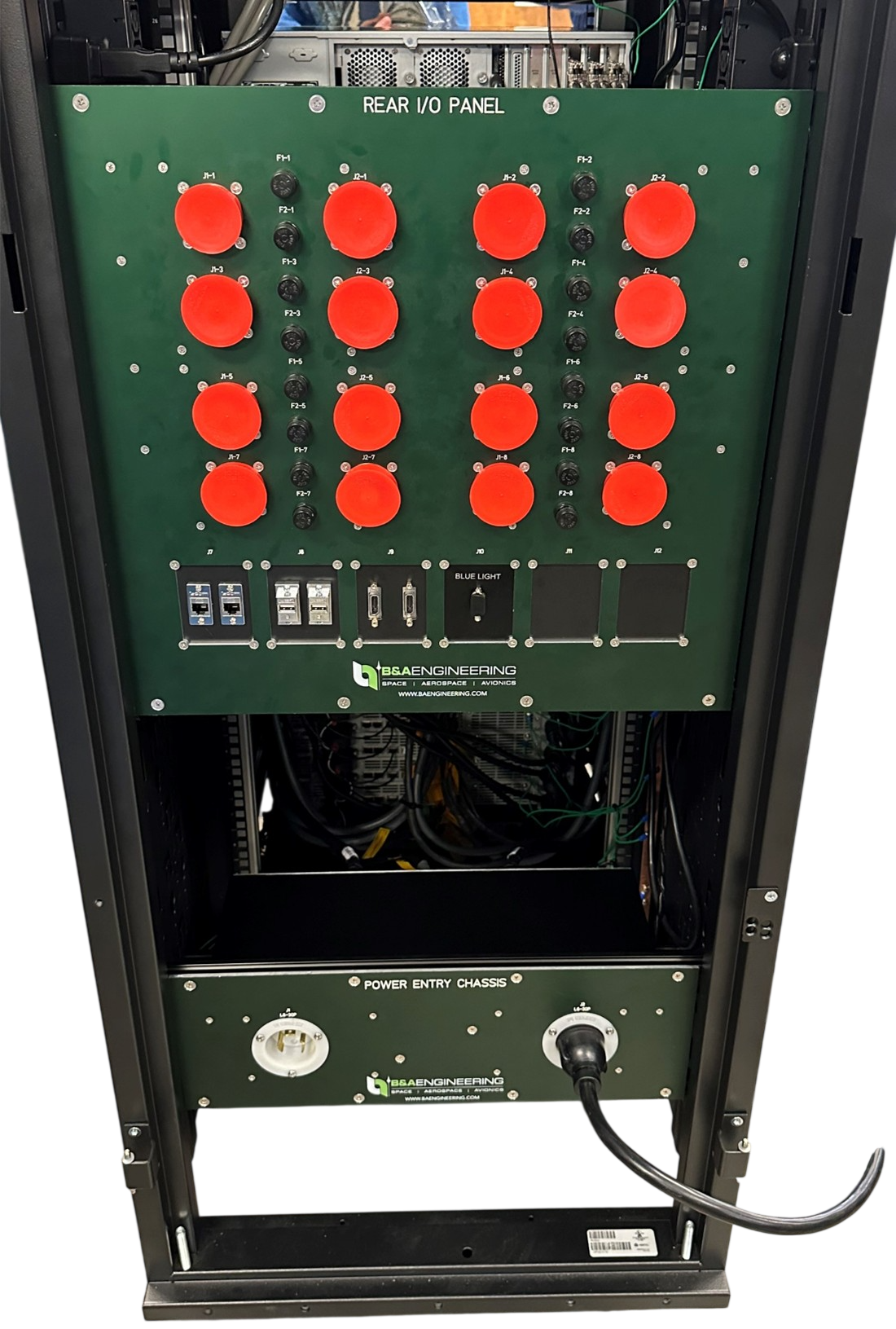
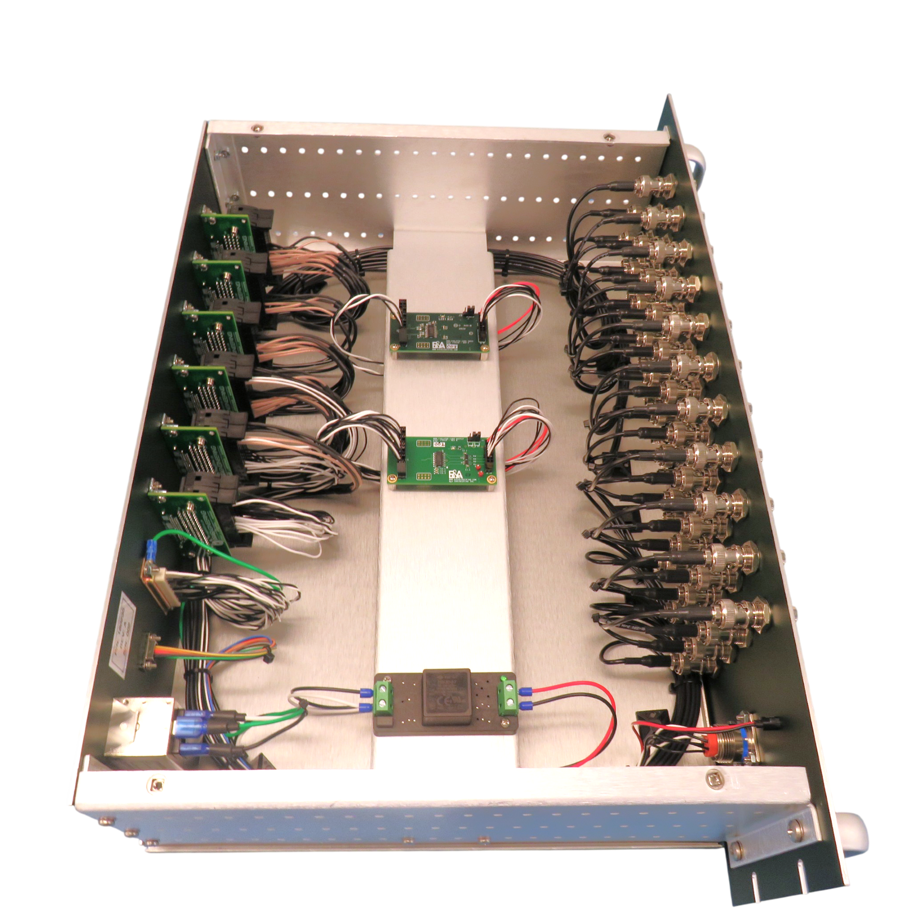
The B&A Interface Chassis provides a centralized connection and routing point between rack instrumentation and the DUT. Signal routing and interconnections are handled within the interface chassis, allowing more standardized COTS cables to be used for internal rack connections and minimizing the need for custom point-to-point cabling. This approach simplifies rack wiring, improves serviceability, and keeps DUT-specific interface requirements contained within a dedicated, organized assembly.

B&A Interface ChassisB&A Interface Chassis installed in the test system rack, providing a clean rack-side connection point for DUT-specific cables.
TEST SYSTEMB&A INTERFACE CHASSISDUT CABLESDUT
COMPLETE SYSTEM DELIVERY

From requirements to a test-ready Test System.

REQUIREMENTS

Interfaces, loads, signals and test objectives.

SYSTEM DESIGN

Architecture, power, protection and interfaces.

BUILD

B&A products, custom chassis, panels and cables.

INTEGRATE

B&A hardware, custom equipment and selected COTS.

VERIFY

Checkout, documentation and delivery.
TEST SYSTEM BUILDING BLOCKS

One test system. Three building blocks.

B&A starts with configurable products, adds application-specific custom hardware, and integrates commercial instrumentation where it adds value.

01 — OUR CONFIGURABLE COTS PRODUCTS

Proven building blocks.

Power entry systems, isolation transformers, emergency power-off, power protection, load systems and B&A-developed SLSC modules.

B&A Configurable COTS Solutions
02 — CUSTOM EQUIPMENT

Designed around the interfaces.

Mission-specific hardware designed and built for the needs of each test system, including custom chassis, interface panels, ITA boxes, breakout hardware, test cables, harnesses, adapters, and other application-specific hardware.

03 — COTS INSTRUMENTS & HARDWARE

Selected and integrated.

Power supplies, DAQ, switching, measurement instruments, computing and network equipment complete the architecture.

NEXT-GENERATION SLSC ARCHITECTURE

A flexible platform for modern test systems.

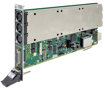
B&A uses the SLSC platform with B&A-developed modules for configurable signal-interface and protection functions.

Digital Isolation
Power Protection
Signal Interface & Routing
Application-Specific I/O
PLaTE SOFTWARE PLATFORM

One software layer that ties the test system together.

Programmable LabVIEW Test Environment (PLaTE)

PLaTE provides the common software framework for controlling and monitoring the test system —        connecting instrumentation, power supplies, B&A hardware, and SLSC modules through one integrated platform.

Prebuilt Driver LibraryIncludes drivers for commonly used instrumentation, programmable power supplies, and B&A SLSC modules.
Expandable by DesignAdditional device and instrument drivers can be developed upon request for program-specific hardware.
Test AutomationAutomated test sequences can be implemented using NI TestStand or Python depending on program requirements and customer preference.
Unified Test System ControlBrings the configurable building blocks together into a consistent operator and automation environment.
INSTRUMENTS+POWER+SLSC+CUSTOM HARDWARE→ PLATE → TEST AUTOMATION
DOCUMENTATION & DELIVERABLES

Engineering documentation delivered with the test system.

B&A can provide the engineering, manufacturing, verification, and user documentation required to support fabrication, integration, checkout, operation, maintenance, and program acceptance. The exact document package can be tailored to customer and program requirements.

01

Test System Top-Level Document

Top-level system document showing the overall test-system architecture and configuration, including system components, bill of materials (BOM), rack stack-up, internal wiring, external connections to the DUT, grounding scheme, power distribution, interfaces, and other key system-level information.

02

Cable & Harness Drawings

Manufacturing drawings, pinouts, connector information, wire definitions, shielding, and cable construction details.

03

Mechanical Drawings

Rack, chassis, panel, mounting, interface, and other mechanical details needed for fabrication and integration.

04

Electrical Schematics

Power distribution, protection, control, signal routing, interconnect, and other system electrical schematics.

05

User Manual

System overview, setup, operation, safety information, interfaces, maintenance guidance, and operator instructions.

06

Checkout Procedure

Step-by-step system checkout and functional verification procedure used before operation or delivery.

07

Verification & Test Reports

Recorded results demonstrating completion of required inspections, functional checks, and system-level verification.

08

Stability / Center-of-Gravity Analysis

Rack stability, center-of-gravity, tip-over, and related mechanical analyses when required by the program.

09

FMEA / Safety Analysis

Failure-mode, protection, and safety analysis documenting key system risks and mitigation features when required.

10

PLaTE Software Manual

Software setup, configuration, driver usage, operation, monitoring, logging, and test-automation guidance.

11

Additional Program Documentation

Customer-specific procedures, interface documents, configuration records, acceptance documentation, or other program deliverables can be included as required.

What does your next Test System need to test?

From standard single racks and mini racks to integrated multi-rack Test Systems.